Working Stress Analysis for Concrete Beams
Consider a relatively long simply supported beam shown below. Assume the load wo to be increasing progressively until the beam fails. The beam will go into the following three stages:
- Uncrack Concrete Stage – at this stage, the gross section of the concrete will resist the bending which means that the beam will behave like a solid beam made entirely of concrete.
- Crack Concrete Stage – Elastic Stress range
- Ultimate Stress Stage – Beam Failure
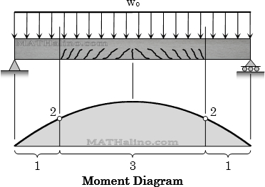
Concrete Beam Crack Stages
At section 1: Uncrack stage
- Actual moment, M < Cracking moment, Mcr
- No cracking occur
- The gross section resists bending
- The tensile stress of concrete is below rupture
At Section 2: Boundary between crack and uncrack stages
- Actual moment, M = Cracking moment, Mcr
- Crack begins to form
- The gross section resists bending
- The tensile stress of concrete reached the rupture point
At Section 3: Crack concrete stage
- Actual moment, M > Cracking moment, Mcr
- Elastic stress stage
- Cracks developed at the tension fiber of the beam and spreads quickly to the neutral axis
- The tensile stress of concrete is higher than the rupture strength
- Ultimate stress stage can occur at failure
Working Stress Analysis – Uncracked Stage
The beam will behave elastically and remains uncracked. The tensile stress of concrete is below rupture.
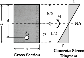
Cracking Moment
NSCP 2010, Section 409.6.2.3
Modulus of rupture of concrete, $f_r = 0.7\sqrt{f'_c} ~ \text{MPa}$
Cracking moment, $M_{cr} = \dfrac{f_r \, I_g}{y_t}$
Where
$I_g$ = Moment of inertia of the gross section neglecting reinforcement
$y_t$ = distance from centroid of gross section to extreme tension fiber
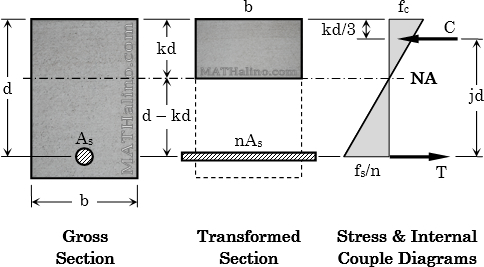
Working Stress Analysis – Cracked Stage
General Requirement
Actual Stresses ≤ Allowable Stresses
Internal Couple Method
Static equilibrium of internal forces
Factor k:
Factor j:
Moment resistance coefficient:
Moment capacity: Use the smallest of the two
$M_s = T \, jd = A_s f_s \, jd$
Transformed Section Method
Convert steel area to equivalent concrete area by multiplying As with modular ratio, n.
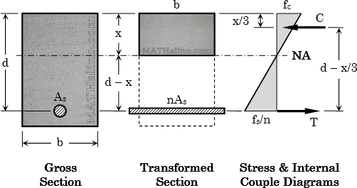
Location of the neutral axis from extreme compression fiber
Doubly reinforced: $\frac{1}{2}bx^2 + (2n - 1)A_s' (x - d') = nA_s(d - x)$
Cracked section moment of inertia (INA = Icr)
Doubly reinforced: $I_{NA} = \dfrac{bx^3}{3} + (2n - 1)A_s'(x - d')^2 + nA_s(d - x)^2$
Actual stresses (calculate using Flexure Formula)
$f_c = \dfrac{Mx}{I_{NA}}$
Tension steel
$\dfrac{f_s}{n} = \dfrac{M(d - x)}{I_{NA}}$
Compression steel for doubly reinforced
$\dfrac{f_s'}{2n} = \dfrac{M(x - d')}{I_{NA}}$
- Add new comment
- 100996 reads