flexural stress

Example 02: Maximum Concentrated Load a Box Beam Can Carry

Problem
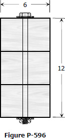
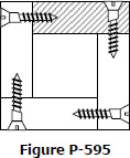
A beam is built up by nailing together 25 mm thick planks to form a 200 mm × 250 mm box section as shown. The nails are spaced 125 mm apart and each can carry a shearing force of up to 1.3 kN. The beam is simply supported for a span of 3.6 m and to carry a concentrated load P at the third point of the span. The allowable shearing stress of the section is 0.827 MPa.
 

spacing-of-bolts-002-box-beam-cross-section.gif


  1. Determine the largest value of P that will not exceed the allowable shearing stress of the beam or the allowable shearing force of the nails.
  2. What is the maximum flexural stress of the beam for the load P computed in Part (1)?


Example 01: Spacing of Screws in Box Beam made from Rectangular Wood

Problem
A concentrated load P is carried at midspan by a simply supported 4-m span beam. The beam is made of 40-mm by 150-mm timber screwed together, as shown. The maximum flexural stress developed is 8.3 MPa and each screw can resist 890 N of shear force.
 

spacing-of-bolts-001-box-beam-cross-section.gif


  1.   Determine the spacing of screws at A.
  2.   Determine the spacing of screws at B.


Example 01: Maximum bending stress, shear stress, and deflection

Problem
A timber beam 4 m long is simply supported at both ends. It carries a uniform load of 10 kN/m including its own weight. The wooden section has a width of 200 mm and a depth of 260 mm and is made up of 80% grade Apitong. Use dressed dimension by reducing its dimensions by 10 mm.

Properties of Apitong
Bending and tension parallel to grain = 16.5 MPa
Shear parallel to grain = 1.73 MPa
Modulus of elasticity in bending = 7.31 GPa
  1. What is the maximum flexural stress of the beam?
  2. What is the maximum shearing stress of the beam?
  3. What is the maximum deflection of the beam?


2006-may-ce-board-stresses-in-timber-beam.gif


Bending Stress and Shearing Stress in Timber Beam

Bending Stress
$f_b = \dfrac{M}{S} = \dfrac{Mc}{I}$
 

Horizontal Shear Stress
$f_v = \dfrac{VQ}{Ib}$

bending-member-corss-section-any-shape.gif
For Rectangular Sections
$f_b = \dfrac{6M}{bd^2}$
 

$f_v = \dfrac{3V}{2bd}$

Problem 1007 | Flexural stresses developed in the wood and steel fibers

Problem 1007
A uniformly distributed load of 300 lb/ft (including the weight of the beam) is simply supported on a 20-ft span. The cross section of the beam is described in Problem 1005. If n = 20, determine the maximum stresses produced in the wood and the steel.
 

Solution to Problem 599 | Spacing of Rivets or Bolts in Built-Up Beams

Problem 599
A beam is formed by bolting together two W200 × 100 sections as shown in Fig. P-599. It is used to support a uniformly distributed load of 30 kN/m (including the weight of the beam) on a simply supported span of 10 m. Compute the maximum flexural stress and the pitch between bolts that have a shearing strength of 30 kN.
 

Wide Flange on top of the other and bolted together


Solution to Problem 598 | Spacing of Rivets or Bolts in Built-Up Beams

Problem 598
As shown in Fig. P-598, two C380 × 60 channels are riveted together by pairs of 19-mm rivets spaced 200 mm apart along the length of the beam. What maximum vertical shear V can be applied to the section without exceeding the stresses given in Illustrative Problem 591?
 

Bolted Back-to-back Channels


Solution to Problem 597 | Spacing of Rivets or Bolts in Built-Up Beams

Problem 597
A plate and angle girder similar to that shown in Fig. 5-32 is fabricated by riveting the short legs of four 125 × 75 × 13 mm angles to a web plate 1000 mm by 10 mm to form a section 1020 mm deep. Cover plates, each 300 mm × 10 mm, are then riveted to the flange angles making the overall height 1040 mm. The moment of inertia of the entire section about the NA is I = 4770 × 106 mm4. Using the allowable stresses specified in Illustrative Problem 591, determine the rivet pitch for 22-mm rivets, attaching the angles to the web plate at a section where V = 450 kN.
 

Built-up Girder from Plate and Angles


Solution to Problem 596 | Spacing of Rivets or Bolts in Built-Up Beams

Problem 596
Three planks 4 in by 6 in., arranged as shown in Fig. P-596 and secured by bolts spaced 1 ft apart, are used to support a concentrated load P at the center of a simply supported span 12 ft long. If P causes a maximum flexural stress of 1200 psi, determine the bolt diameters, assuming that the shear between the planks is transmitted by friction only. The bolts are tightened to a tension of 20 ksi and the coefficient of friction between the planks is 0.40.
 

Three Planks Secured by Bolts


Solution to Problem 595 | Spacing of Rivets or Bolts in Built-Up Beams

Problem 595
A concentrated load P is carried at midspan of a simply supported 12-ft span. The beam is made of 2-in. by 6-in. pieces screwed together, as shown in Fig. P-595. If the maximum flexural stress developed is 1400 psi, find the maximum shearing stress and the pitch of the screws if each screw can resist 200 lb.
 

595-box-beam-held-by-screws.jpg


Pages

Subscribe to RSS - flexural stress