Design for Flexure and Shear
To determine the load capacity or the size of beam section, it must satisfy the allowable stresses in both flexure (bending) and shear. Shearing stress usually governs in the design of short beams that are heavily loaded, while flexure is usually the governing stress for long beams. In material comparison, timber is low in shear strength than that of steel.
- Read more about Design for Flexure and Shear
- Log in or register to post comments
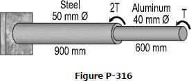
316 Permissible Torque That Can Be Applied to a Compound Shaft
Problem 316
A compound shaft consisting of a steel segment and an aluminum segment is acted upon by two torques as shown in Fig. P-316. Determine the maximum permissible value of T subject to the following conditions: τst ≤ 83 MPa, τal ≤ 55 MPa, and the angle of rotation of the free end is limited to 6°. For steel, G = 83 GPa and for aluminum, G = 28 GPa.
309 Finding the Diameter of a Propeller Shaft Transmitting a Power
Problem 309
A steel propeller shaft is to transmit 4.5 MW at 3 Hz without exceeding a shearing stress of 50 MPa or twisting through more than 1° in a length of 26 diameters. Compute the proper diameter if G = 83 GPa.
308 Maximum Horsepower That Can be Transmitted by Steel Shaft
Problem 308
A 2-in-diameter steel shaft rotates at 240 rpm. If the shearing stress is limited to 12 ksi, determine the maximum horsepower that can be transmitted.
306 Maximum Shearing Stress of Marine Propeller Shaft
Problem 306
A steel marine propeller shaft 14 in. in diameter and 18 ft long is used to transmit 5000 hp at 189 rpm. If G = 12 × 106 psi, determine the maximum shearing stress.
- Read more about 306 Maximum Shearing Stress of Marine Propeller Shaft
- Log in or register to post comments
305 Minimum Diameter of Steel Shaft With Allowable Angle of Twist
Problem 305
What is the minimum diameter of a solid steel shaft that will not twist through more than 3° in a 6-m length when subjected to a torque of 12 kN·m? What maximum shearing stress is developed? Use G = 83 GPa.
Solution to Problem 240 Statically Indeterminate
Problem 240
Three steel eye-bars, each 4 in. by 1 in. in section, are to be assembled by driving rigid 7/8-in.-diameter drift pins through holes drilled in the ends of the bars. The center-line spacing between the holes is 30 ft in the two outer bars, but 0.045 in. shorter in the middle bar. Find the shearing stress developed in the drip pins. Neglect local deformation at the holes.
- Read more about Solution to Problem 240 Statically Indeterminate
- Log in or register to post comments
Solution to Problem 131 Bearing Stress
Problem 131
Repeat Problem 130 if the rivet diameter is 22 mm and all other data remain unchanged.
- Read more about Solution to Problem 131 Bearing Stress
- Log in or register to post comments
Solution to Problem 130 Bearing Stress
Problem 130
Figure P-130 shows a roof truss and the detail of the riveted connection at joint B. Using allowable stresses of τ = 70 MPa and σb= 140 MPa, how many 19-mm-diameter rivets are required to fasten member BC to the gusset plate? Member BE? What is the largest average tensile or compressive stress in BC and BE?
- Read more about Solution to Problem 130 Bearing Stress
- 2 comments
- Log in or register to post comments
Solution to Problem 129 Bearing Stress
Problem 129
- Read more about Solution to Problem 129 Bearing Stress
- Log in or register to post comments