Wide-Flange
Solution to Problem 599 | Spacing of Rivets or Bolts in Built-Up Beams
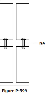
Problem 599
A beam is formed by bolting together two W200 × 100 sections as shown in Fig. P-599. It is used to support a uniformly distributed load of 30 kN/m (including the weight of the beam) on a simply supported span of 10 m. Compute the maximum flexural stress and the pitch between bolts that have a shearing strength of 30 kN.
Solution to Problem 592 | Spacing of Rivets or Bolts in Built-Up Beams
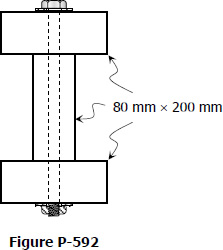
Problem 592
A wide flange section is formed by bolting together three planks, each 80 mm by 200 mm, arranged as shown in Fig. P-592. If each bolt can withstand a shearing force of 8 kN, determine the pitch if the beam is loaded so as to cause a maximum shearing stress of 1.4 MPa.
Solution to Problem 588 | Design for Flexure and Shear
Problem 588
The distributed load shown in Fig. P-588 is supported by a wide-flange section of the given dimensions. Determine the maximum value of wo that will not exceed a flexural stress of 10 MPa or a shearing stress of 1.0 MPa.
Solution to Problem 584 | Design for Flexure and Shear
Problem 584
A wide-flange section having the dimensions shown in Fig. P-584 supports a distributed load of wo lb/ft on a simple span of length L ft. Determine the ratio of the maximum flexural stress to the maximum shear stress.
- Read more about Solution to Problem 584 | Design for Flexure and Shear
- Log in or register to post comments
Solution to Problem 576 | Horizontal Shearing Stress
Problem 576
Rework Prob. 575 assuming that the web is 200 mm instead of 160 mm.
- Read more about Solution to Problem 576 | Horizontal Shearing Stress
- Log in or register to post comments
Solution to Problem 575 | Horizontal Shearing Stress
Problem 575
Determine the maximum and minimum shearing stress in the web of the wide flange section in Fig. P-575 if V = 100 kN. Also, compute the percentage of vertical shear carried only by the web of the beam.
- Read more about Solution to Problem 575 | Horizontal Shearing Stress
- Log in or register to post comments
Solution to Problem 560 | Built-up Beams
Problem 560
The wide-flange beam shown in Fig. P-560 is strengthened by bolting two cover plates 160 mm by 20 mm to the top and bottom flanges. If the maximum flexure stress is 140 MPa, compute the total force (a) in each cover plate and (b) in each flange. Neglect the weakening effect of the bolt holes.
- Read more about Solution to Problem 560 | Built-up Beams
- Log in or register to post comments
Solution to Problem 543 | Floor Framing
Problem 543
A portion of the floor plan of a building is shown in Fig. P-543. The total loading (including live and dead loads) in each bay is as shown. Select the lightest suitable W-shape if the allowable flexural stress is 120 MPa.
- Read more about Solution to Problem 543 | Floor Framing
- Log in or register to post comments
For Girders (G - 2) | Solution to Problem 542
Contents
For Girders (G - 2)
 $S_{required} = \dfrac{M}{f_b} = \dfrac{120(1000^2)}{120}$
$S_{required} = 1000 \times 10^3 \, \text{mm}^3$
- Read more about For Girders (G - 2) | Solution to Problem 542
- Log in or register to post comments