aluminum rod

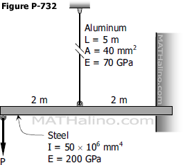
Problem 733 | Cantilever beam with moment load at the free end and supported by a rod at midspan

Problem 733
The load P in Prob. 732 is replaced by a counterclockwise couple M. Determine the maximum value of M if the stress in the vertical rod is not to exceed 150 MPa.
 

Problem 732 | Cantilever beam supported by a cable at midspan

Problem 732
The midpoint of the steel in Fig. P-732 is connected to the vertical aluminum rod. Determine the maximum value of P if the stress in the rod is not to exceed 120 MPa.
 

Cantilever beam supported with aluminum rod at the midspan


Solution to Problem 268 Thermal Stress

Problem 268
The rigid bar ABC in Fig. P-268 is pinned at B and attached to the two vertical rods. Initially, the bar is horizontal and the vertical rods are stress-free. Determine the stress in the aluminum rod if the temperature of the steel rod is decreased by 40°C. Neglect the weight of bar ABC.
 

268 Steel and aluminum rods


Solution to Problem 242 Statically Indeterminate

Problem 242
The assembly in Fig. P-242 consists of a light rigid bar AB, pinned at O, that is attached to the steel and aluminum rods. In the position shown, bar AB is horizontal and there is a gap, Δ = 5 mm, between the lower end of the steel rod and its pin support at C. Compute the stress in the aluminum rod when the lower end of the steel rod is attached to its support.
 

Figure 242


Solution to Problem 239 Statically Indeterminate

Problem 239
The rigid platform in Fig. P-239 has negligible mass and rests on two steel bars, each 250.00 mm long. The center bar is aluminum and 249.90 mm long. Compute the stress in the aluminum bar after the center load P = 400 kN has been applied. For each steel bar, the area is 1200 mm2 and E = 200 GPa. For the aluminum bar, the area is 2400 mm2 and E = 70 GPa.
 

Figure 239


Solution to Problem 216 Axial Deformation

Problem 216
As shown in Fig. P-216, two aluminum rods AB and BC, hinged to rigid supports, are pinned together at B to carry a vertical load P = 6000 lb. If each rod has a cross-sectional area of 0.60 in.2 and E = 10 × 106 psi, compute the elongation of each rod and the horizontal and vertical displacements of point B. Assume α = 30° and θ = 30°.
 

Figure P-216 and P-217


Solution to Problem 215 Axial Deformation

Problem 215
A uniform concrete slab of total weight W is to be attached, as shown in Fig. P-215, to two rods whose lower ends are on the same level. Determine the ratio of the areas of the rods so that the slab will remain level.
 

Figure P-215


Solution 215

Solution to Problem 214 Axial Deformation

Problem 214
The rigid bars AB and CD shown in Fig. P-214 are supported by pins at A and C and the two rods. Determine the maximum force P that can be applied as shown if its vertical movement is limited to 5 mm. Neglect the weights of all members.
 

Figure P-214


Solution to Problem 213 Axial Deformation

Problem 213
The rigid bar AB, attached to two vertical rods as shown in Fig. P-213, is horizontal before the load P is applied. Determine the vertical movement of P if its magnitude is 50 kN.
 

Figure P-213


Subscribe to RSS - aluminum rod