October 2008

Bearing Stress

Bearing stress is the contact pressure between the separate bodies. It differs from compressive stress, as it is an internal stress caused by compressive forces.
 

$\sigma_b = \dfrac{P_b}{A_b}$


000-plates-pin-bearing.gif


Solution to Problem 125 Bearing Stress

Problem 125

In Fig. 1-12, assume that a 20-mm-diameter rivet joins the plates that are each 110 mm wide. The allowable stresses are 120 MPa for bearing in the plate material and 60 MPa for shearing of rivet. Determine (a) the minimum thickness of each plate; and (b) the largest average tensile stress in the plates.
 

Solution to Problem 126 Bearing Stress

Problem 126
The lap joint shown in Fig. P-126 is fastened by four ¾-in.-diameter rivets. Calculate the maximum safe load P that can be applied if the shearing stress in the rivets is limited to 14 ksi and the bearing stress in the plates is limited to 18 ksi. Assume the applied load is uniformly distributed among the four rivets.
 

126-plates-four-rivets.gif


Solution to Problem 127 Bearing Stress

Problem 127
In the clevis shown in Fig. 1-11b, find the minimum bolt diameter and the minimum thickness of each yoke that will support a load P = 14 kips without exceeding a shearing stress of 12 ksi and a bearing stress of 20 ksi.
 

127-clevis-double-shear-bolt.gif


Solution to Problem 130 Bearing Stress

Problem 130
Figure P-130 shows a roof truss and the detail of the riveted connection at joint B. Using allowable stresses of τ = 70 MPa and σb= 140 MPa, how many 19-mm-diameter rivets are required to fasten member BC to the gusset plate? Member BE? What is the largest average tensile or compressive stress in BC and BE?
 

130-simple-truss.gif


Solution to Problem 131 Bearing Stress

Problem 131
Repeat Problem 130 if the rivet diameter is 22 mm and all other data remain unchanged.
 

Thin-walled Pressure Vessels

A tank or pipe carrying a fluid or gas under a pressure is subjected to tensile forces, which resist bursting, developed across longitudinal and transverse sections.
 

TANGENTIAL STRESS, σt (Circumferential Stress)
Consider the tank shown being subjected to an internal pressure p. The length of the tank is L and the wall thickness is t. Isolating the right half of the tank:
 

Solution to Problem 133 Pressure Vessel

Problem 133
A cylindrical steel pressure vessel 400 mm in diameter with a wall thickness of 20 mm, is subjected to an internal pressure of 4.5 MN/m2. (a) Calculate the tangential and longitudinal stresses in the steel. (b) To what value may the internal pressure be increased if the stress in the steel is limited to 120 MN/m2? (c) If the internal pressure were increased until the vessel burst, sketch the type of fracture that would occur.
 

Solution to Problem 134 Pressure Vessel

Problem 134
The wall thickness of a 4-ft-diameter spherical tank is 5/16 inch. Calculate the allowable internal pressure if the stress is limited to 8000 psi.
 

Solution to Problem 135 Pressure Vessel

Problem 135
Calculate the minimum wall thickness for a cylindrical vessel that is to carry a gas at a pressure of 1400 psi. The diameter of the vessel is 2 ft, and the stress is limited to 12 ksi.
 

Solution to Problem 136 Pressure Vessel

Problem 136
A cylindrical pressure vessel is fabricated from steel plating that has a thickness of 20 mm. The diameter of the pressure vessel is 450 mm and its length is 2.0 m. Determine the maximum internal pressure that can be applied if the longitudinal stress is limited to 140 MPa, and the circumferential stress is limited to 60 MPa.
 

Solution 136
Based on circumferential stress (tangential):
 

Solution to Problem 137 Pressure Vessel

Problem 137
A water tank, 22 ft in diameter, is made from steel plates that are 1/2 in. thick. Find the maximum height to which the tank may be filled if the circumferential stress is limited to 6000 psi. The specific weight of water is 62.4 lb/ft3.
 

Solution to Problem 138 Pressure Vessel

Problem 138
The strength of longitudinal joint in Fig. 1-17 is 33 kips/ft, whereas for the girth is 16 kips/ft. Calculate the maximum diameter of the cylinder tank if the internal pressure is 150 psi.
 

Solution to Problem 139 Pressure Vessel

Problem 139
Find the limiting peripheral velocity of a rotating steel ring if the allowable stress is 20 ksi and steel weighs 490 lb/ft3. At what revolutions per minute (rpm) will the stress reach 30 ksi if the mean radius is 10 in.?
 

Solution to Problem 140 Pressure Vessel

Problem 140
At what angular velocity will the stress of the rotating steel ring equal 150 MPa if its mean radius is 220 mm? The density of steel 7.85 Mg/m3.
 

Solution 140
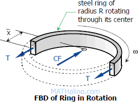
140-fbd-rotating-ring.gif$CF = M \omega^2 \bar x$
 

Where:
$M = \rho V = \rho A \pi R$

$x = 2R / \pi$


Thus,
$CF = \rho A \pi R \omega^2 (2R / \pi)$

Solution to Problem 141 Pressure Vessel

Problem 141
The tank shown in Fig. P-141 is fabricated from 1/8-in steel plate. Calculate the maximum longitudinal and circumferential stress caused by an internal pressure of 125 psi.
 

141-flat-oval-tank.gif


Solution to Problem 142 Pressure Vessel

Problem 142
A pipe carrying steam at 3.5 MPa has an outside diameter of 450 mm and a wall thickness of 10 mm. A gasket is inserted between the flange at one end of the pipe and a flat plate used to cap the end. How many 40-mm-diameter bolts must be used to hold the cap on if the allowable stress in the bolts is 80 MPa, of which 55 MPa is the initial stress? What circumferential stress is developed in the pipe? Why is it necessary to tighten the bolt initially, and what will happen if the steam pressure should cause the stress in the bolts to be twice the value of the initial stress?
 

Strain

  1. Simple Strain
  2. Stress-Strain Diagram
  3. Axial Deformation
  4. Shearing Deformation
  5. Poisson's Ratio
  6. Statically Indeterminate Members
  7. Thermal Stress

Simple Strain

Also known as unit deformation, strain is the ratio of the change in length caused by the applied force, to the original length.
 

Simple strain


$\varepsilon = \dfrac{\delta}{L}$

where δ is the deformation and L is the original length, thus ε is dimensionless.
 

Stress-strain Diagram

Suppose that a metal specimen be placed in tension-compression-testing machine. As the axial load is gradually increased in increments, the total elongation over the gauge length is measured at each increment of the load and this is continued until failure of the specimen takes place. Knowing the original cross-sectional area and length of the specimen, the normal stress σ and the strain ε can be obtained. The graph of these quantities with the stress σ along the y-axis and the strain ε along the x-axis is called the stress-strain diagram. The stress-strain diagram differs in form for various materials. The diagram shown below is that for a medium-carbon structural steel.
 

Axial Deformation

In the linear portion of the stress-strain diagram, the tress is proportional to strain and is given by
 

$\sigma = E \varepsilon$


since $\sigma = P / A$ and $\varepsilon = \delta / L$, then $\dfrac{P}{A} = E \dfrac{\delta}{L}$
 

$\delta = \dfrac{PL}{AE} = \dfrac{\sigma L}{E}$

To use this formula, the load must be axial, the bar must have a uniform cross-sectional area, and the stress must not exceed the proportional limit.
 

Solution to Problem 203 Stress-strain Diagram

Problem 203
The following data were recorded during the tensile test of a 14-mm-diameter mild steel rod. The gage length was 50 mm.
 

Load (N) Elongation (mm) Load (N) Elongation (mm)
0 0 46 200 1.25
6 310 0.010 52 400 2.50
12 600 0.020 58 500 4.50
18 800 0.030 68 000 7.50
25 100 0.040 59 000 12.5
31 300 0.050 67 800 15.5
37 900 0.060 65 000 20.0
40 100 0.163 65 500 Fracture
41 600 0.433


Plot the stress-strain diagram and determine the following mechanical properties: (a) proportional limits; (b) modulus of elasticity; (c) yield point; (d) ultimate strength; and (e) rupture strength.
 

Pages